Difference between revisions of "Realistic Fire Simulation"
| Line 26: | Line 26: | ||
== Code == | == Code == | ||
| + | |||
| + | For schematic 1, with all LEDs logically inverted: | ||
<pre> | <pre> | ||
int p1 = 0; // Set the 3 pins with PWM | int p1 = 0; // Set the 3 pins with PWM | ||
| Line 53: | Line 55: | ||
| − | + | For schematic 2 (reusing the LED attached to Pin 1, which is not "logically inverted"): | |
| + | <pre> | ||
| + | int p1 = 0; // Set the 3 pins with PWM | ||
| + | int p2 = 1; | ||
| + | int p3 = 4; | ||
| + | |||
| + | void setup() { | ||
| + | pinMode(p1, OUTPUT); // Set the pins as output | ||
| + | pinMode(p2, OUTPUT); | ||
| + | pinMode(p3, OUTPUT); | ||
| + | } | ||
| + | |||
| + | void loop() { | ||
| + | int v1, v2, v3; | ||
| + | |||
| + | v1 = random(155) + 100; // Calculate the new light | ||
| + | v2 = random(155) + 100; // intensity values for each LED | ||
| + | v3 = random(155) + 100; | ||
| + | |||
| + | analogWrite(p1, 255 - v1); // Apply the light intensity to each LED | ||
| + | analogWrite(p2, v2); // This LED is not "logically inverted" | ||
| + | analogWrite(p3, 255 - v3); | ||
| + | |||
| + | delay(20 + random(80)); // Wait some random time for next udpate | ||
| + | } | ||
| + | </pre> | ||
| + | |||
| + | |||
| + | == Final Result == | ||
{{#evt: | {{#evt: | ||
Revision as of 20:31, 4 January 2016
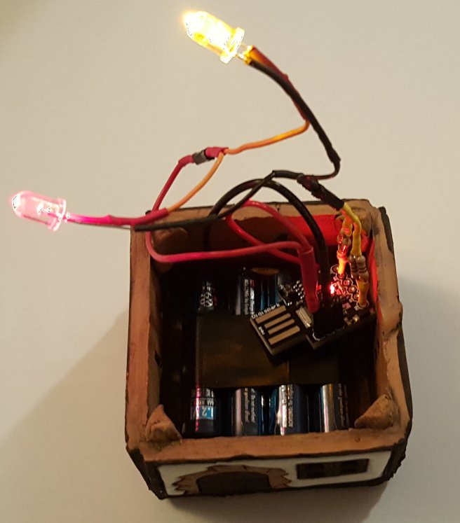
In this page is described how to create a realistic flickering fire effect with LEDs and an Arduino board. In this case I used a Digispark due to its small size.
The intention is to give some light to a small clay decoration house, one of those prepared for lighting a small candle inside and evaporate water with essence. Instead of using a candle I put a simple battery with some LEDs inside but it looked too boring so I tried to imitate the movement of a candle inside it. Here it is described the design and process followed.
Component Schematics
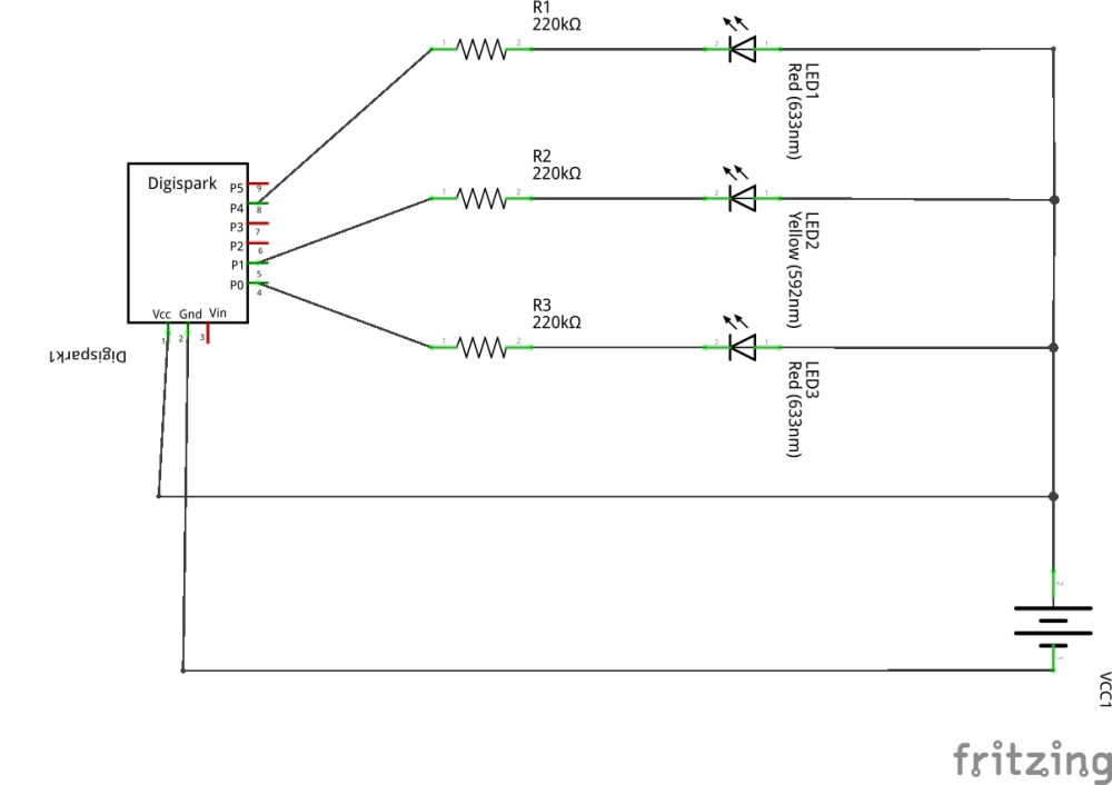
The three LEDs (two reds and one yellow - I guess one red and two yellows would also look nice) are connected to the PWM ports of the arduino (Digispark, which has exactly 3 PwM pins).
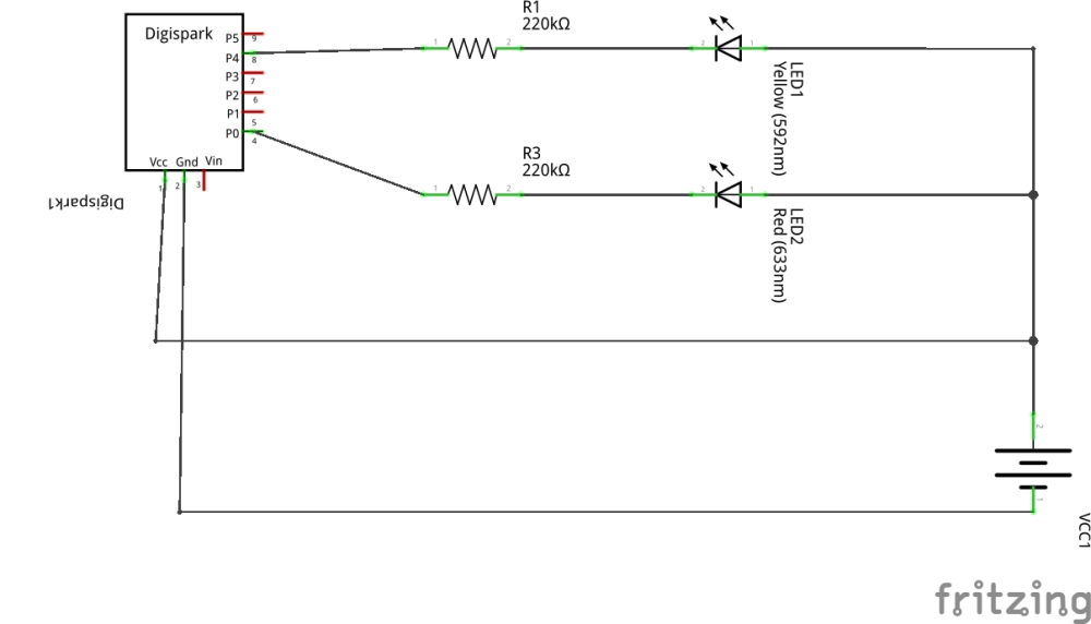
The pin P1 of the Digispark board already has red LED attached to it, so there is no need to add a new one, or to remove the current one. For this reason the new schematics is:
Building
Code
For schematic 1, with all LEDs logically inverted:
int p1 = 0; // Set the 3 pins with PWM
int p2 = 1;
int p3 = 4;

void setup() {
  pinMode(p1, OUTPUT); // Set the pins as output
  pinMode(p2, OUTPUT);
  pinMode(p3, OUTPUT);
}

void loop() {
  int v1, v2, v3;

  v1 = random(155) + 100; // Calculate the new light
  v2 = random(155) + 100; // intensity values for each LED
  v3 = random(155) + 100;

  analogWrite(p1, 255 - v1); // Apply the light intensity
  analogWrite(p2, 255 - v2); // to each LED
  analogWrite(p3, 255 - v3);

  delay(20 + random(80)); // Wait some random time for next udpate
}
For schematic 2 (reusing the LED attached to Pin 1, which is not "logically inverted"):
int p1 = 0; // Set the 3 pins with PWM
int p2 = 1;
int p3 = 4;

void setup() {
  pinMode(p1, OUTPUT); // Set the pins as output
  pinMode(p2, OUTPUT);
  pinMode(p3, OUTPUT);
}

void loop() {
  int v1, v2, v3;

  v1 = random(155) + 100; // Calculate the new light
  v2 = random(155) + 100; // intensity values for each LED
  v3 = random(155) + 100;

  analogWrite(p1, 255 - v1); // Apply the light intensity to each  LED
  analogWrite(p2, v2);       // This LED is not "logically inverted"
  analogWrite(p3, 255 - v3);

  delay(20 + random(80)); // Wait some random time for next udpate
}
