Difference between revisions of "Arduino Environment and Esp8266"
(→Installation) |
|||
| Line 18: | Line 18: | ||
[[File:esp8266_arduino_03.png]] | [[File:esp8266_arduino_03.png]] | ||
| − | == | + | = Test Programs = |
| + | |||
| + | == Blink == | ||
| + | This example makes the led attached to pin 16 (D0 of the NodeMCU 1.0 board) blink and prints the number of iterations done in the serial terminal. | ||
| + | For the pin mapping see [[NodeMCU#Pin_Mapping_for_Arduino_IDE]] | ||
<syntaxhighlight lang="C" line="1" > | <syntaxhighlight lang="C" line="1" > | ||
| Line 44: | Line 48: | ||
</syntaxhighlight> | </syntaxhighlight> | ||
| − | == | + | == Connecting to Wifi Access Point == |
| − | |||
| − | |||
| − | |||
| − | |||
| − | |||
| − | |||
| − | |||
| − | |||
| − | |||
| − | |||
| − | |||
| − | |||
| − | |||
| − | |||
Revision as of 15:48, 26 April 2016
Installation
Arduino IDE 1.6.x or newer is needed (I tried it on version 1.6.8).
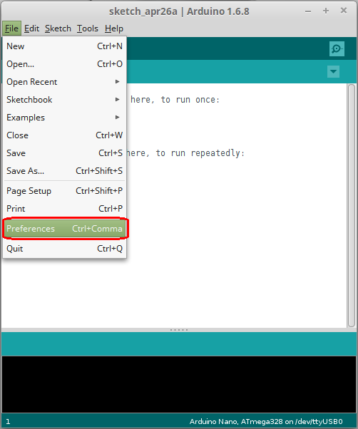
- Open the Arduino IDE and go to "File -> Preferences"
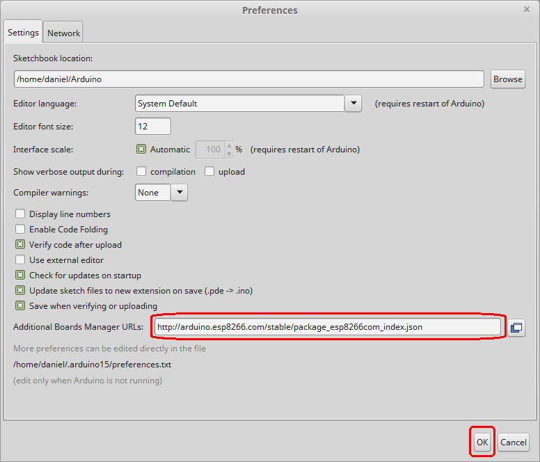
- In the field "Additional Boards Manager URLs" introduce
http://arduino.esp8266.com/stable/package_esp8266com_index.jsonand click OK.
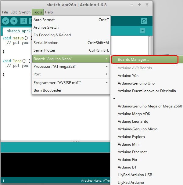
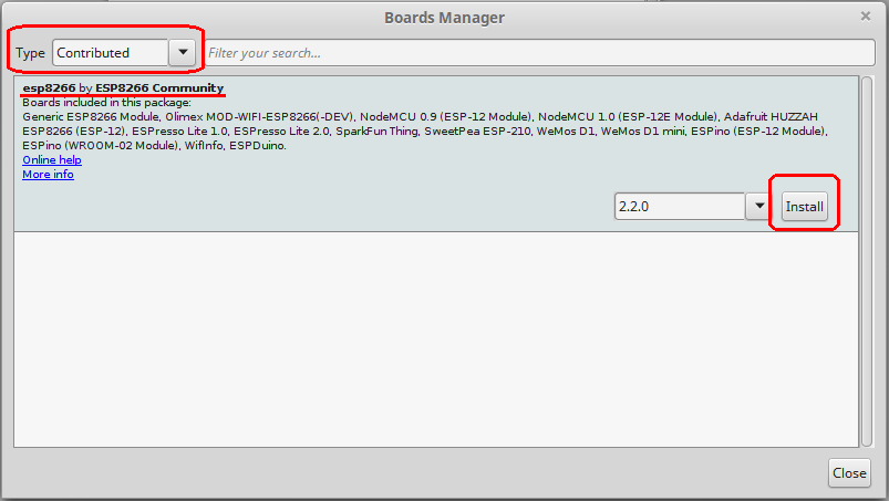
- Then go to "Tools -> Boards -> Boards Manager" and in the box "Type" select “Contributed”. Select the “esp8266 by ESP8266 Community” package and click the “Install” button.
- Now you can select the board for developing from "Tools -> Boards->ESP8266 Modules" and choose the board you want to program.
Test Programs
Blink
This example makes the led attached to pin 16 (D0 of the NodeMCU 1.0 board) blink and prints the number of iterations done in the serial terminal. For the pin mapping see NodeMCU#Pin_Mapping_for_Arduino_IDE
 1 int pin = 16; // D0 pin in NodeMCU
 2 int i = 0;
 3
 4 // the setup function runs once when you press reset or power the board
 5 void setup() {
 6   Serial.begin(115200);
 7
 8   // initialize digital pin 16 (D0) as an output.
 9   pinMode(pin, OUTPUT);
10 }
11
12 // the loop function runs over and over again forever
13 void loop() {
14   Serial.print("Line ");
15   Serial.println(i);
16   i++;
17   digitalWrite(pin, HIGH);   // turn the LED on (HIGH is the voltage level)
18   delay(100);              // wait for a second
19   digitalWrite(pin, LOW);    // turn the LED off by making the voltage LOW
20   delay(900);              // wait for a second
21 }


