Difference between revisions of "Using external programmers (USBasp)"
(→Usage) |
|||
| Line 38: | Line 38: | ||
== Usage == | == Usage == | ||
| − | The next picture shows the cables connected to an | + | The next picture shows the cables connected to an ATmega328p on a breadboard connected to the USBasp programmer, ready to be used. |
[[File:usbasp_atmega.jpg]] | [[File:usbasp_atmega.jpg]] | ||
| + | |||
| + | |||
| + | Then select the USBasp programmer in the Arduino IDE: | ||
| + | |||
| + | [[File:usbasp_arduino1.png]] | ||
| + | |||
| + | |||
| + | And programming it using this option of the menu (or pressing CONTROL+SHIFT+U): | ||
| + | |||
| + | [[File:usbasp_arduino2.png]] | ||
| + | |||
| + | |||
| + | For the uploaded program to work, the atmega328p will need extra hardware (such as the 16MHz clock) or we can use the internal RC oscillator by configure the FUSE bits accordingly. If the clock is different that the one of the board selected probably it is a good idea to create our own board for the Arduino IDE so that the functions that depend on the timings work correctly. An example of this can be seen in the description of the [[Custom RBOT Board]] | ||
Latest revision as of 17:43, 13 April 2016
Sometimes one will need to program an Arduino board that does not have a programming interface or will want to build a custom one using and Atmel AVR chip. If the chip contains no bootloader or we do not have a serial interface we can use an external ICSP programmer, such as the USBasp. In this page we will explain how to use such programmer.
USBasp description
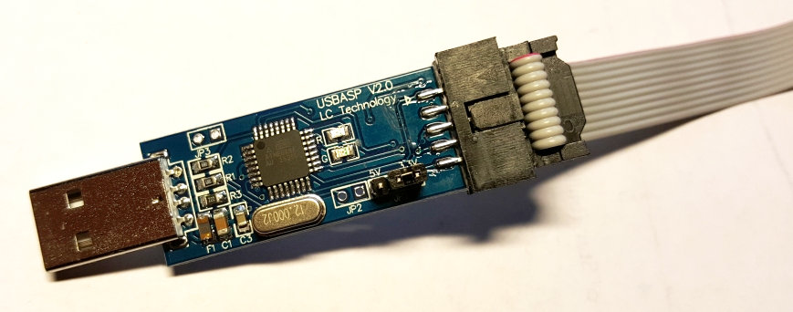
USBasp is a USB in-circuit programmer for Atmel AVR controllers. The programmer uses a firmware-only USB driver, no special USB controller is needed.
Features:
- Works under multiple platforms such as GNU/Linux, Mac OS X.
- Allows you to read or write the microcontroller EEPROM, firmware, fuse bits and lock bits.
- No special controllers or smd components are needed.
- Programming speed is up to 5kBytes/sec.
- SCK option to support targets with low clock speed (< 1,5MHz).
- 10 pin ISP interface (conforms to standard ISP 10-pin pinout).
More info: http://www.fischl.de/usbasp/
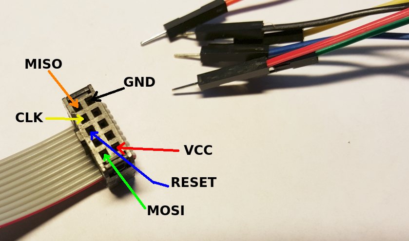
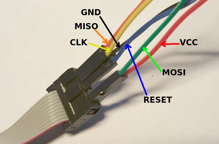
10 pin ISP interface
Male Interface:
Female Interface:
- Red: VCC
- Black: GND
- Blue: RST (to AVR reset pin)
- Green: MOSI (to AVR SPI's master output pin)
- Orange: MISO (to AVR SPI's master input pin)
- Yellow: SCK (to AVR SPI's sync serial clock pin)
Usage
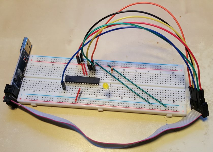
The next picture shows the cables connected to an ATmega328p on a breadboard connected to the USBasp programmer, ready to be used.
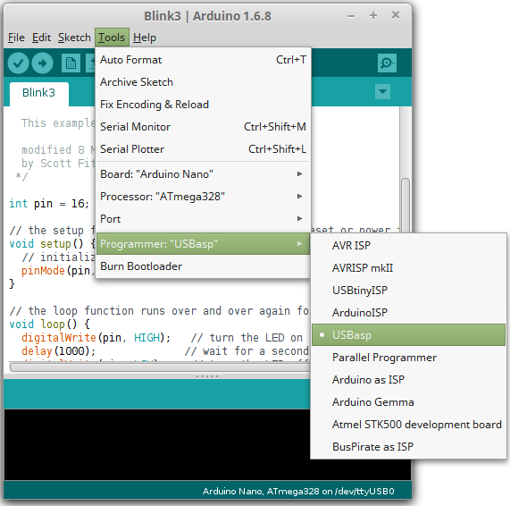
Then select the USBasp programmer in the Arduino IDE:
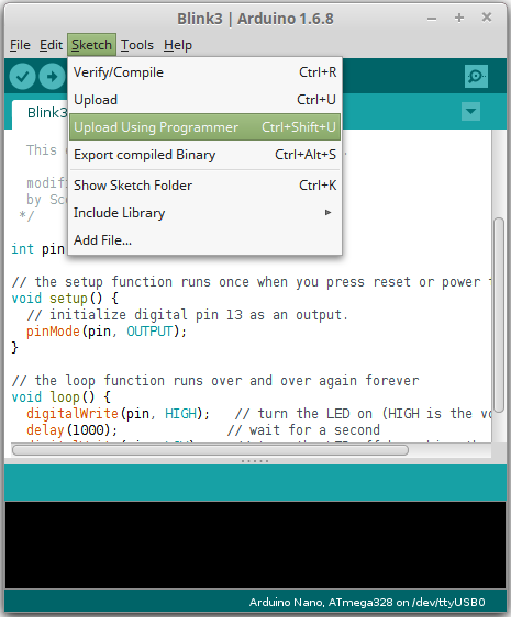
And programming it using this option of the menu (or pressing CONTROL+SHIFT+U):
For the uploaded program to work, the atmega328p will need extra hardware (such as the 16MHz clock) or we can use the internal RC oscillator by configure the FUSE bits accordingly. If the clock is different that the one of the board selected probably it is a good idea to create our own board for the Arduino IDE so that the functions that depend on the timings work correctly. An example of this can be seen in the description of the Custom RBOT Board
